Contact Us
What does a drilling mud motor diagram look like?
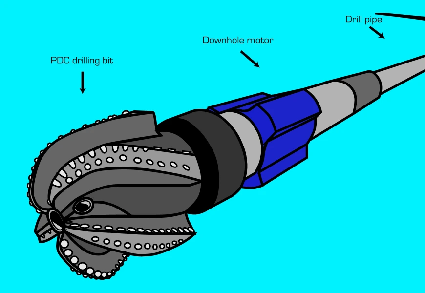
A drilling mud motor diagram typically includes the power section, transmission, lower end, and sometimes, drill bit. It is used by application engineers and drilling engineers when designing assemblies for vertical and directional drilling. Here is an example of a drilling mud motor diagram:

All Pro FAQs
Recent Articles

September 22, 2025
Beating the AFE Every Time: What 3.56 Days of Drilling Efficiency Actually Means
September 22, 2025
ProDirectional’s RSS Expertise: Proven Performance When You Choose Rotary Steerable

May 28, 2025
Why Best Value Beats Lowest Price in Directional Drilling

April 21, 2025
Automation in Directional Drilling: Why People Still Matter and How GUIDE ROC Delivers Both

February 20, 2025
Turning Up The Heat: Providing Reliability in Hot Hole Environments
November 6, 2024
Built, Not Bought: The ProDirectional Advantage in MWD Services and Technology
March 21, 2024
A leap forward in rotary steerable system connectivity

March 21, 2024
What client success looks like at ProDirectional

January 31, 2024
How does a mud motor work?

September 13, 2023